
By FabRapid · September 18, 2026
Your plastic prototype fits the assembly. The mounting holes line up, and you can reach the screws. Now you need a metal version to test under load. Should you machine it, or send the same model to a metal 3D printing service?
Start with CNC machining when the design has accessible features and you want to test a specified stock alloy. Consider metal 3D printing when an internal passage or a difficult shape is essential to the test. If the printed part needs accurate mating faces or bores, include machining in the plan.
Here, metal 3D printing means laser powder bed fusion, the process family used by services described as DMLS or SLM. A laser melts metal powder in successive layers. It has different design requirements from the desktop plastic printer you may have used for the first model. Renishaw explains the powder-based process and its geometry options.
In this guide:
- Define what the metal prototype must prove
- Compare geometry and machining access
- Specify fits, materials and finishing
- Compare complete quotes and prepare your files
- Work through a bracket example and common questions
Define what the next prototype must prove
Write a sentence describing the next test before requesting a quote. For example: "Check whether the motor mount keeps the shaft aligned at the intended load." That gives you a reason to care about the mounting face, bore location and test conditions.
A plastic assembly model can answer useful questions about size and access. It does not establish how the eventual metal part will behave. Record which questions you have already answered, then identify the measurements you still need from the metal version.
If you expect to machine the production part, a machined prototype in the intended alloy and condition gives you a more representative starting point. Protolabs discusses this connection between prototype and production in its metal prototyping guide. A successful test still applies to the design, material and manufacturing condition you actually tested.
Keep the acceptance criteria beside the CAD revision. Decide what would make you approve the design, and what result would send it back for another iteration. A part that arrives without a test plan can become an expensive assembly mock-up.
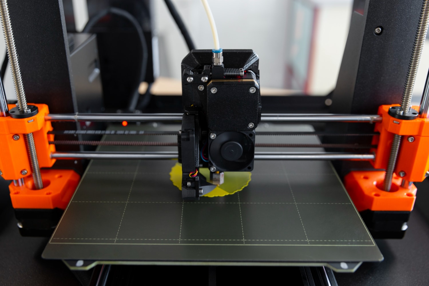
A plastic print can help check the assembly before ordering metal. This image shows filament printing, a different process from laser powder bed fusion.
CNC or metal 3D printing: a first-pass comparison
Use this table to decide which process to discuss first. It is a screening tool; a supplier still needs to review the actual model and drawing.
What your prototype needs | Route to discuss first | Question to resolve before ordering |
|---|---|---|
Open pockets, holes and accessible faces | CNC machining | Can the tools reach each feature while the part is held securely? |
A passage that curves inside the part | Metal 3D printing | Can the passage be built, cleared of powder and inspected? |
A specified wrought alloy and temper | CNC from suitable stock | Will the supplied material and condition match the drawing? |
A complex printed body with precision interfaces | Printing followed by machining | Which surfaces need machining allowance and fixture access? |
A production-representative test | The planned production route | Which differences remain between this prototype and production? |
Check geometry before comparing prices
For a CNC quote, trace how a cutter would reach every feature. Pay attention to deep pockets, undercuts and internal corners. A rotating end mill leaves a radius at an internal pocket corner; specifying a square corner may require a different operation or a design change. Protolabs' CNC design guide illustrates corner reliefs and the cost implications of small cutters.
Ask whether an internal radius can grow without affecting the assembly. If it can, give the supplier that freedom. If the mating part genuinely requires a sharp corner, show the interface so the requirement is clear. The CNC machining page is a useful starting point for discussing the available operations.
Laser powder bed fusion can produce internal channels and shapes that are difficult to cut from stock. It also needs a build strategy. Orientation affects support placement, and support removal needs physical access. Internal spaces require a way to remove loose powder and verify the result. These constraints belong in the design review, as described in the DMLS design guide.
Before requesting a DMLS review, mark the feature that makes printing worth considering. Ask the supplier to explain how that feature will be finished and checked. A hidden passage that cannot be cleaned or inspected may need another revision before it is ready to manufacture.
Put the important fits on a drawing
A CAD model shows nominal geometry. Your drawing should explain which deviations matter. Identify the surfaces that locate the part in the assembly, then specify the dimensions and tolerances that control those relationships.
For a bearing housing, that might mean the bearing seat and its relationship to the mounting face. For a cover, it could be the sealing surface and fastener pattern. Choose the requirements from the function of the part. Avoid assigning a tight tolerance everywhere because one feature needs it.
Printed metal can be machined after the build. Milling, reaming or tapping may be needed for particular interfaces; Protolabs describes examples of this combined approach in its discussion of additive and CNC processes. Ask the supplier which features will remain as printed and which will receive a separate operation.
Agree on machining allowance and workholding before printing. Include surface finish requirements where they affect the test, and specify how the finished dimensions will be inspected. If you request anodizing or another finish, state whether the dimensional requirements apply after finishing and identify any areas that need masking.
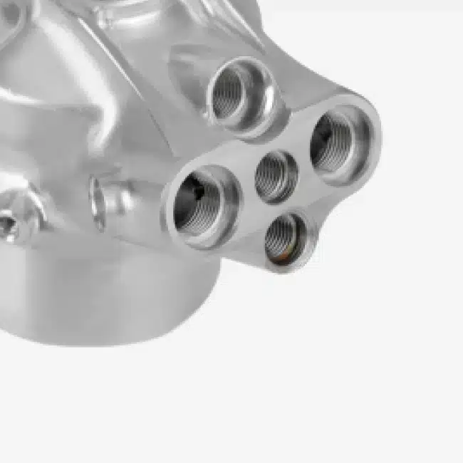
Threaded ports and mating surfaces deserve explicit requirements. The outer shape alone does not describe how a component must fit.
Name the alloy and its condition
"Aluminum" is too broad for a test specification. A quote for machined 6061-T6 and a quote for printed AlSi10Mg describe different materials. Treat a substitution as an engineering decision and record it in the test report.
6061 is a wrought aluminum alloy. Its T6 designation indicates solution heat treatment and artificial aging, as explained in Hydro's 6061-T6 material information. AlSi10Mg is a separate alloy used for metal powder bed fusion. The EOS AlSi10Mg data sheet describes how heat treatment can change its properties and cautions that actual part properties depend on the process.
Ask for the material designation and delivered condition on each quote. If a supplier proposes an alternative, check whether it still lets you answer the intended test question. You may accept an alternative for an assembly check while keeping the specified material for a later performance test.
Our aluminum material page can help frame the material discussion. Final selection should use the requirements of your component and the documentation for the material being supplied.
Compare the cost of a part ready to test
Request quotes for the same delivery state. A printed blank and a machined, finished, inspected component leave you with different amounts of work.
Have each supplier identify what is included in the quoted price. For a printed part, ask about support removal, heat treatment and any machining after the build. For either route, confirm finishing and inspection. Ask who handles each operation and whether it is included in the delivery date.
Use the date you can assemble and test the part as your scheduling target. Tell the supplier when the test is booked, whether partial delivery would help, and which requirements are fixed. Do not compare one supplier's machine time with another supplier's complete delivery schedule.
If another batch is likely, quote that quantity separately. Keep the CAD revision, material and inspection scope identical so the comparison remains useful. There is no universal quantity at which one process becomes cheaper for every design.
Files and notes to send with the request
- A current solid CAD model, preferably STEP, with units and revision identified. Confirm the supplier's accepted formats.
- A drawing showing functional dimensions, tolerances, datums where needed, and thread specifications.
- The material grade and delivered condition, plus any alternatives you are willing to review.
- Finishing requirements and the dimensions or surfaces that must be inspected after finishing.
- The prototype quantity, any expected follow-up batch, and the date the parts are needed for testing.
- A short description of the test, with an assembly image if it helps explain a difficult interface.
Keep the model and drawing on the same revision. If you change a hole after requesting a quote, send the revised files together and ask for the quote to be updated.
A bracket example: let the test decide
Consider a hypothetical motor bracket with a flat mounting base, accessible holes and an open pocket. You have printed it in plastic to check clearance. The next test concerns alignment under load, and the intended production material is 6061-T6.
CNC machining would be the first route to quote for this example. Give the supplier the mounting relationship and material requirement, then review any corner radii or pocket changes they propose. Record the dimensions you will measure before and after the test.
Now suppose the design changes to include a curved internal cooling passage. That creates a reason to investigate metal printing. The review must cover passage cleaning and inspection, the proposed alloy, and machining of the mounting interfaces. Those changes also need to be reflected in the test plan. This is an illustrative decision exercise, not a customer case study.
Common questions before the first metal order
Can I send the STL from my plastic prototype?
Ask which files the supplier needs. Keep the original solid CAD model available for manufacturing review and revisions. Send a drawing for functional requirements that the model alone does not communicate. Identify units explicitly.
Is a printed metal part always weaker than a machined one?
No. Process names alone cannot establish how two parts will perform. Compare the actual alloy, delivered condition and relevant test data. For a performance-critical decision, agree on the evidence needed for your particular component.
Can I use CNC and printing on the same prototype?
Yes. A printed body can receive machined interfaces. Ask for one manufacturing plan covering both operations, including how the part will be located and held for machining. Confirm who is responsible for the finished dimensions.
Discuss your first metal version with FabRapid
Contact FabRapid about your prototype with the current CAD revision, a drawing and a sentence explaining the next test. If you are considering both CNC and metal printing, identify the feature or material requirement driving that choice. Include the date you need the part ready for assembly so the process discussion starts with the work you actually need done.